The GTEM chamber is a type of equipment used for electromagnetic compatibility (EMC) testing. Compared to the TEM chamber, the frequency will be higher, above the GHZ frequency. Compared with anechoic chambers, the cost is much lower. Therefore, GTEM chambers have been widely used in the field of electromagnetic compatibility in recent years
The full name of GTEM Cell is the gigahertz transverse electromagnetic wave transmission cell, which is a newly developed technology in the field of electromagnetic compatibility for broadband measurement and evaluation of the electromagnetic compatibility performance of the tested equipment. It inherits the advantages of low loss, uniform field strength, and accurate and adjustable field strength of TEM cells, while absorbing the advantages of high measurable frequencies such as anechoic chambers. At the same time, it also compensates for the limitations of TEM cells on the upper frequency limit and the inverse relationship between internal volume and usable frequency limit. The frequency range of GTEM cells can range from DC to several GHz or more, and its internal volume to overall ratio is large. The size limitation of the tested object is independent of frequency, and there are no special requirements for the external environment when used. Therefore, GTEM cells are applied for wide frequency range radiation emission and radiation immunity testing.
The EMC testing system composed of GTEM room can save a lot of money compared to using antenna radiation, reception and other testing methods in anechoic chambers and open areas. It eliminates the requirement for external testing environment conditions, requires lower instrument and equipment power, and can improve measurement speed several times, making it easy to achieve automated measurement.
Especially for EMC testing of small test objects, the measurement scheme of GTEM room is a cost-effective testing scheme.
GTEM Cell structure design
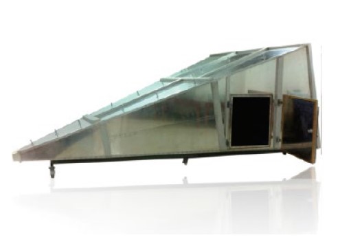
GTEMThe chamber is a device designed based on the principle of coaxial and asymmetric rectangular transmission lines. In order to avoid reflection and resonance of internal electromagnetic waves, it is designed to be tapered in shape, and its input end adopts an N-type coaxial joint. Then the center conductor is flattened into a sector-shaped plate, called a core plate. A rectangular uniform field area is formed between the core plate and the bottom plate.
GTEMThe interior of the chamber structure takes on a shape similar to a rectangular parallelepiped. There is an opening at the top and bottom to allow test equipment to pass through and connect to the test equipment's cables. At the same time, the sidewalls of the GTEM chamber were also perforated for installation of test equipment and probes.
GTEM Cell testing
EUT includes automotive electronics, ICs and other electronic products. Conduct immunity testing and radiated emission testing. The test is based on the following standards:
(1)YD/T 1690.2-2007 "Communications Industry Standards of the People's Republic of China"-Technical requirements and measurement methods for diagnosis of internal electromagnetic emissions from telecommunications equipment (150KHz ~1GHz)-Part 2: Measurement of radiated emissionsTEM celland broadbandTEM cellmethod
(2)IEC 61967-2: Integrated circuits - Measurement of electromagnetic emissions, 150 kHz to 1GHz -Part 2: Measurement of radiated emissions, TEM-cell method and wideband TEM-cell method (150 kHz to 8 GHz)
(3)IEC62132-2 Integrated circuits – Measurement of electromagnetic immunity –Part 2: Measurement of radiated immunity – TEM cell and wideband TEM cell method
(4)GB/T 17626.20-2014 Electromagnetic Compatibility, Testing and Measurement Technology Emission and immunity testing in transverse electromagnetic wave (TEM) waveguides
(5)GJB151B-2013 "Requirements and measurements for electromagnetic emissions and sensitivity of equipment and subsystems"-RS105 Transient electromagnetic field radiation sensitivity
(6)ISO 11452-3/SAE J1113-24 "Test Method for Electronic Interference Components of Road Vehicles Using Narrow-Band Emission Electromagnetic Energy"-TEM Cell method
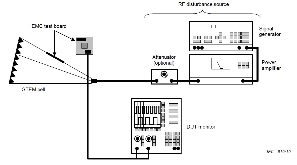
Radiated emission and radiated immunity are consistent with the TEM cell test configuration. The following is a schematic diagram of the GTEM chamber radiation immunity test.
The full name of GTEM Cell is the gigahertz transverse electromagnetic wave transmission cell, which is a newly developed technology in the field of electromagnetic compatibility for broadband measurement and evaluation of the electromagnetic compatibility performance of the tested equipment. It inherits the advantages of low loss, uniform field strength, and accurate and adjustable field strength of TEM cells, while absorbing the advantages of high measurable frequencies such as anechoic chambers. At the same time, it also compensates for the limitations of TEM cells on the upper frequency limit and the inverse relationship between internal volume and usable frequency limit. The frequency range of GTEM cells can range from DC to several GHz or more, and its internal volume to overall ratio is large. The size limitation of the tested object is independent of frequency, and there are no special requirements for the external environment when used. Therefore, GTEM cells are applied for wide frequency range radiation emission and radiation immunity testing.
The EMC testing system composed of GTEM room can save a lot of money compared to using antenna radiation, reception and other testing methods in anechoic chambers and open areas. It eliminates the requirement for external testing environment conditions, requires lower instrument and equipment power, and can improve measurement speed several times, making it easy to achieve automated measurement.
Especially for EMC testing of small test objects, the measurement scheme of GTEM room is a cost-effective testing scheme.
GTEM Cell structure design
GTEMThe chamber is a device designed based on the principle of coaxial and asymmetric rectangular transmission lines. In order to avoid reflection and resonance of internal electromagnetic waves, it is designed to be tapered in shape, and its input end adopts an N-type coaxial joint. Then the center conductor is flattened into a sector-shaped plate, called a core plate. A rectangular uniform field area is formed between the core plate and the bottom plate.
GTEMThe interior of the chamber structure takes on a shape similar to a rectangular parallelepiped. There is an opening at the top and bottom to allow test equipment to pass through and connect to the test equipment's cables. At the same time, the sidewalls of the GTEM chamber were also perforated for installation of test equipment and probes.
GTEM Cell testing
EUT includes automotive electronics, ICs and other electronic products. Conduct immunity testing and radiated emission testing. The test is based on the following standards:
(1)YD/T 1690.2-2007 "Communications Industry Standards of the People's Republic of China"-Technical requirements and measurement methods for diagnosis of internal electromagnetic emissions from telecommunications equipment (150KHz ~1GHz)-Part 2: Measurement of radiated emissionsTEM celland broadbandTEM cellmethod
(2)IEC 61967-2: Integrated circuits - Measurement of electromagnetic emissions, 150 kHz to 1GHz -Part 2: Measurement of radiated emissions, TEM-cell method and wideband TEM-cell method (150 kHz to 8 GHz)
(3)IEC62132-2 Integrated circuits – Measurement of electromagnetic immunity –Part 2: Measurement of radiated immunity – TEM cell and wideband TEM cell method
(4)GB/T 17626.20-2014 Electromagnetic Compatibility, Testing and Measurement Technology Emission and immunity testing in transverse electromagnetic wave (TEM) waveguides
(5)GJB151B-2013 "Requirements and measurements for electromagnetic emissions and sensitivity of equipment and subsystems"-RS105 Transient electromagnetic field radiation sensitivity
(6)ISO 11452-3/SAE J1113-24 "Test Method for Electronic Interference Components of Road Vehicles Using Narrow-Band Emission Electromagnetic Energy"-TEM Cell method
Radiated emission and radiated immunity are consistent with the TEM cell test configuration. The following is a schematic diagram of the GTEM chamber radiation immunity test.
Product parameters
| product size | 1.2m*0.64m*0.4m | 3m*1.65m*1.1m |
| frequency range | DC-18GHz | |
| Uniform field area | 200*200*150mm | 400*400*300mm |
| VSWR | 1.2:1 | |
2025年4月24日 星期四 8时59分46秒

 粤公网安备44030002005678号


